Cantilever Gate System
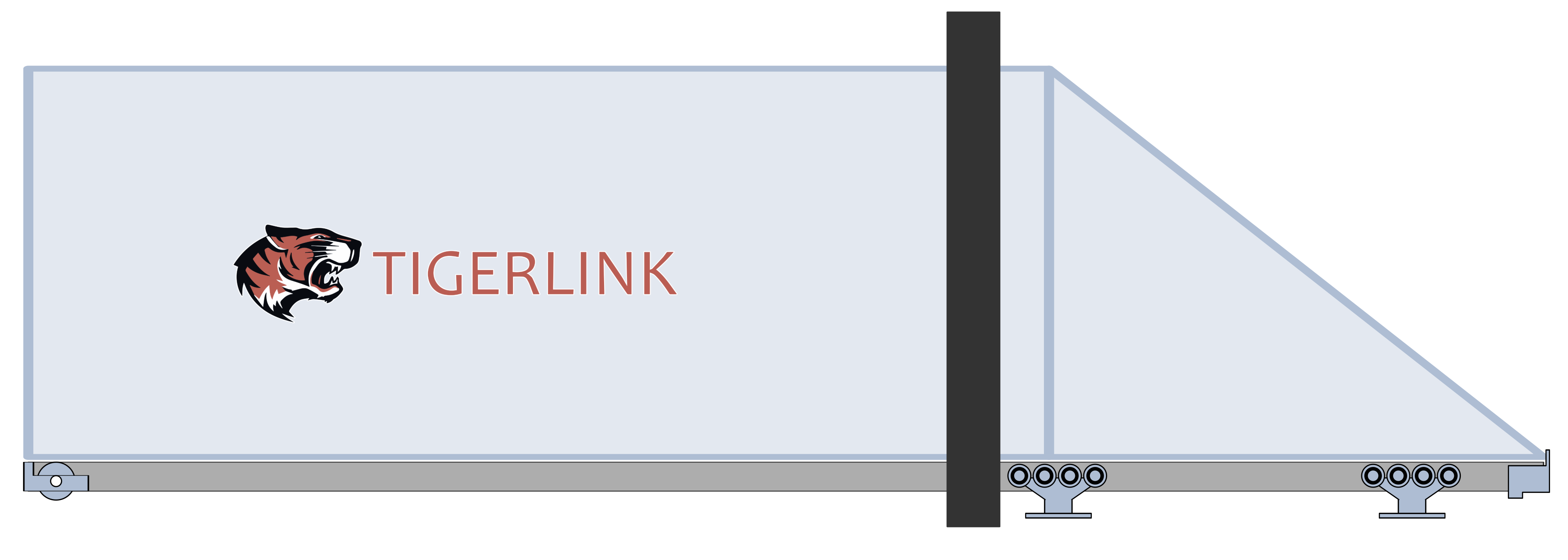
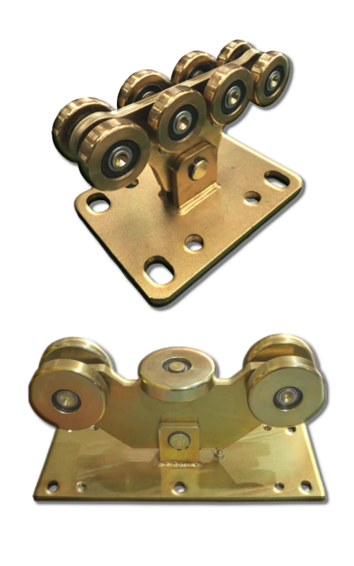
A cantilever gate is a sliding driveway gate that "floats" across an opening without touching the ground. It is supported by counterbalanced carriage rollers attached to the concrete footing underground on one side, eliminating the need for a bottom floor track or traditional wheels along the driveway.
Cantilever Gate Dimensions Calculator
Enter gate opening and weight to look up the recommended dimensions.

Gate Length | Tail Length | Footing Length | Footing Depth

Wheel Spacing | Footing Depth | Footing Width | Footing Length
Cantilever Gate Dimensions Calculator
Enter gate opening and weight to look up the recommended dimensions.
Gate Length | Tail Length | Footing Length | Footing Depth
Wheel Spacing | Footing Depth | Footing Width | Footing Length
Cantilever gates are a popular solution for driveways, commercial entrances and industrial sites where a traditional ground-track sliding gate may not be suitable. Unlike conventional sliding gates, a cantilever gate is supported from one side and runs above the ground without a floor track. This makes it ideal for uneven surfaces, driveways made of bricks or tiles, pebbles and asphalt surfaces and areas where dirt, leaves, or debris could interfere with a floor track.
A complete cantilever gate system consists of several key components working together to support, guide and move the gate smoothly. The main components include the cantilever track, carriage wheels, gate holders, guide wheels and track end caps. The correct combination of components depends on the gate’s overall width, weight and intended application.
At Tigerlink, we offer cantilever gate components for a range of residential and commercial applications, from compact gates up to heavy-duty systems. Our component sets are available in different sizes and weight capacities. The 2 main variations are the 8-wheel carriage wheels and the 5-wheel carriage wheels.
Whether you’re building a new cantilever sliding gate or replacing existing hardware, selecting components with the correct load capacity is essential for smooth, reliable and long-lasting operation.
How it actually carries its own weight:
- The gate panel is only part of the full structure. Behind the leading post, the gate frame extends further back as a counterbalance tail — often triangular or truss-shaped, tapering back from full gate height down to the roller line. The longer the gate panel requires proportionately longer tail.
- This rear tail extension acts as a lever arm: as the gate rolls to the closing position, the weight of the underground concrete footing attached to the tail and the gate panel counterbalance each other across the support posts, similar to a seesaw, which is why it can "float" over the driveway with no ground track.
What actually supports it:
- Mounted on the ground are carriage wheels — unlike traditional wheels, these wheels are actually stationary and the cantilever track welded along the bottom-side of the gate panel and extension tail moves over them instead.
- Beneath the carriage wheels sits a substantial underground concrete footing, because it has to balance out the tipping forces created by the cantilevered weight of the gate panel.
Why it's used:
- No floor track means no tripping hazard and heavy-equipment and forklift can easily drive through. No debris or leaves on the track means a smoother movement of the gate and operation of the gate motor. It just gives an overall cleaner look to the driveway.
- Because there's no floor track and the gate panel is not touching the ground, it handles uneven surfaces of the driveway better than the standard floor-track-guided sliding gate.
The trade-off:
- All of that counter balance support has to come from somewhere. Hence, the oversized underground concrete footing, the rear tail, and the wheel-spacing distance could significantly scale up both the installation costs and the space requirement for the system to work.